
Page 57 - Plastics News Issue September2025
P. 57
TECHNOLOGY NEWS
Building a Screw-Cooling System
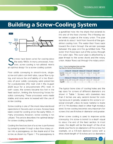
a gundrilled hole into the shank that extends to
the end of the feed channel. The inflowing wa-
ter enters a pipe at the rotary union. The pipe
extends to about 1 inch from the end of the gun-
drilled cooling hole. The water then flows back
toward the shank through the annular passage
between the pipe and the gundrilled hole. The
water then flows back out of the screw, through
the outer pipe. This outer pipe is attached by a
pipe thread to the screw shank and the rotary
crews have been cored for cooling since
the early 1960s. In many processes, how- union. Water flows out through the rotary union.
Sever, screw cooling is not utilized. Here’s
an optimal design for a screw-cooling system.
Poor solids conveying in smooth-bore, single-
screw extruders can limit rates, cause flow surg-
ing, and reduce the profitability of a line. Exam-
ples of poor solids conveying were presented
for a polystyrene (PS) resin and in the August
2025 issue for a polycarbonate (PC) resin. In
both cases, the screws became too hot in the The typical bore sizes of cooling holes and the
feed section, limiting the forwarding forces for tap sizes for screws of different diameters are
solids conveying. These processes were made shown in Table 1. Screws with diameters less
stable, and rates were increased with the use of than 2 inches are very seldom bored for cool-
screw cooling. ing because it greatly weakens the screw’s tor-
sional strength unless its base material is made
Screw cooling is one of the most misunderstood of 17-4 PH stainless steel or other high modulus
operations in the extrusion process. Screws have steel. Screw cooling becomes very important for
been cored for cooling since the early 1960s. In screws that are 8 inches in diameter and greater.
many processes, however, screw cooling is not
utilized. This article describes the optimal design When screw cooling is used to improve solids
for screw-cooling systems. conveying, the screw is bored to a depth equal
to about the end of the feed section. In most
Cooling the feed section of a screw is performed cases, the depth will be the length of the drive
by pumping water through a duo-flow rotary un- shank plus five to six diameters of the screw. For
ion into a passageway on the shank end of the example, on a 4.5-inch diameter screw with a
screw, as shown by Figure 1. The passageway is drive shank length of 16 inches and six diameters
September 2025 PLASTICS NEWS 57