
Page 58 - Plastics News Issue September2025
P. 58
TECHNOLOGY NEWS
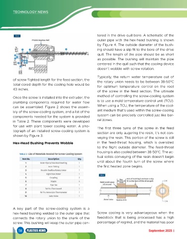
tered in the drive quill bore. A schematic of the
outer pipe with the hex-head bushing is shown
by Figure 4. The outside diameter of the bush-
ing should have a slip fit to the bore of the drive
quill. The length of the pipe should be as short
as possible. The bushing will maintain the pipe
centered in the quill such that the cooling device
doesn’t wobble with screw rotation.
Typically, the return water temperature out of
of screw flighted length for the feed section, the the rotary union needs to be between 38-50 C
0
total cored depth for the cooling hole would be for optimum temperature control on the root
43 inches.
of the screw in the feed section. The ultimate
Once the screw is installed into the extruder, the method of controlling the screw-cooling system
plumbing components required for water flow is to use a mold temperature control unit (TCU).
can be assembled. Figure 2 shows the assem- When using a TCU, the temperature of the cool-
bly of the screw-cooling system, and a list of the ant medium that’s used within the screw-cooling
components needed for the system is provided system can be precisely controlled just like bar-
in Table 2. These components were developed rel zones.
for use with plant tower cooling water. A pho- The first three turns of the screw in the feed
tograph of an installed screw-cooling system is section are only augering the resin, it’s not con-
shown by Figure 3.
veying the resin. This portion of the screw is still
Hex-Head Bushing Prevents Wobble in the feed-throat housing, which is oversized
to the flight outside diameter. The feed-throat
housing is also cooled between 38-50 C. The ac-
0
tual solids conveying of the resin doesn’t begin
until about the fourth turn of the screw where
the first heated zone begins.
A key part of the screw-cooling system is a
hex-head bushing welded to the outer pipe that Screw cooling is very advantageous when the
connects the rotary union to the shank of the feedstock that is being processed has a high
screw. This bushing will keep the outer pipe cen- percentage of regrind, and the material has poor
58 PLASTICS NEWS September 2025